What are you looking for?
Injection molding part design for metal injection molding is the process of shaping a metal component so it can be filled as a powder-binder feedstock, released from the mold, debound without internal damage, sintered with predictable shrinkage, and finished to the drawing at production volume. The geometry must work through every stage, not just look manufacturable in a 3D model.
This distinction is essential because MIM combines the geometric freedom of injection molding with the thermal behavior of powder metallurgy. The Metal Powder Industries Federation describes MIM feedstock as using fine metal powder, typically below 20 micrometers, mixed with binder. After molding, binder is removed and the part is sintered. During sintering the powder skeleton densifies, so the tool is intentionally larger than the final component and the supplier must compensate for process-specific shrinkage.
Good MIM design therefore balances six linked objectives: complete mold filling, easy ejection, efficient debinding, uniform sintering, stable dimensional control, and low secondary-processing cost. A feature that is easy to mold but creates a thick isolated mass can distort during debinding or sintering. A tolerance that looks modest on a machined part can become expensive if it forces grinding after MIM. An undercut that eliminates an assembly may be worth a sliding tool, while a decorative undercut may only add tooling risk.
Hengji’s current MIM page positions the process for small, complex metal components and highlights near-net-shape manufacture, dimensional precision, and reduced secondary processing. The practical way to use those advantages is to review the drawing before tooling. This guide provides a structured checklist for engineers and sourcing teams so they can identify geometry risks early and ask more useful questions during supplier selection.
Injection molding part design in MIM is the coordinated design of geometry, tooling access, feedstock flow, debinding path, sintering support, shrink compensation, tolerance, and finishing so a complex metal part can be produced repeatedly.
Plastic injection molding experience is useful, but MIM is not simply plastic molding with a different material. The molded green part contains a high volume fraction of metal powder held by binder. The binder must later leave the part, and the remaining powder skeleton must survive handling and sintering. Dimensions then change as the component densifies.
As a result, the designer should think in manufacturing stages. In the mold, the questions are fill, pressure, knit lines, gate witness, draft, parting line, ejection, and tool complexity. During debinding, the questions are section thickness, binder-removal distance, support, and defect risk. During sintering, the questions are shrinkage, gravity, friction against setters, mass distribution, distortion, and final microstructure. After sintering, the questions are tolerance, surface, heat treatment, machining, coating, and inspection.
A successful drawing communicates which dimensions are genuinely critical and which can follow normal process capability. This matters because MIM can create complex shapes economically, but forcing machining-level tolerances onto every dimension can remove the cost advantage. The engineer should reserve tight tolerances for features that control fit, sealing, gear mesh, alignment, motion, or safety.
Early collaboration also helps with part consolidation. MIM can integrate bosses, ribs, slots, teeth, flats, logos, textured areas, and other features that might require multiple machining or assembly operations in conventional manufacturing. The design benefit is greatest when added complexity replaces purchased components or secondary operations rather than adding complexity for appearance alone.
Injection molding part design for MIM must account for predictable but process-specific sintering shrinkage by scaling tooling and controlling geometry, feedstock, debinding, furnace conditions, and support.
Sintering shrinkage occurs because the porous powder skeleton densifies as particles bond. The shrink factor depends on the alloy, particle characteristics, solids loading, binder system, molding conditions, debinding history, furnace cycle, atmosphere, geometry, and orientation. There is no safe universal percentage that can be copied from one supplier or feedstock to another.
That is why a MIM supplier develops a shrink factor for each material-process combination and then refines local compensation from tool trials. MPIF conference material-development descriptions treat shrink factor, density, and sintered mechanical properties as formal outputs of material development. This is a more reliable model than asking the customer to manually scale the CAD file.
The designer’s job is to make shrinkage as uniform as practical. Symmetrical geometry and balanced mass distribution generally reduce differential movement. Thick-to-thin transitions, large isolated bosses, offset heavy sections, unsupported spans, and nonuniform ribs can produce different local thermal histories and shrink behavior. The tool may still compensate for some predictable movement, but simpler thermal behavior usually produces a wider process window.
Datums should be chosen with the process route in mind. If a critical bore will be machined after sintering, the machining datum and allowance should be defined. If two as-sintered features control assembly, their relationship may be more important than either absolute dimension. Geometric tolerancing should communicate functional relationships so the supplier can select the best fixtures and inspection method.
When a supplier reviews injection molding part design for an automotive component, the review should include the final assembly condition, not only the standalone part. Mating pins, shafts, housings, fasteners, coatings, and thermal expansion can determine which dimensions deserve the tightest control.
Injection molding part design should use the thinnest practical and most uniform wall distribution that fills reliably, survives debinding, maintains stiffness, and avoids unnecessary material and sintering time.
Uniform walls are valuable because they promote more consistent filling, binder removal, heating, and shrinkage. A thick solid block next to a thin arm can create a large difference in thermal mass. During molding, the thin arm may freeze early while the thick area continues to pack. During debinding, binder must travel farther out of the thick area. During sintering, the two sections may densify and move differently.
If a heavy solid section is not functionally necessary, coring is often better than leaving a large mass. Ribs can restore stiffness without filling the entire volume with expensive feedstock. A hollow or cored structure also reduces material cost, which matters because feedstock is a significant component of MIM piece price.
Transitions should be gradual. Fillets reduce stress concentration and improve feedstock flow around corners. Sharp internal corners are difficult to tool and can create local stress. Sudden section changes can produce sink-like behavior in the green part, flow hesitation, or differential shrinkage. The fillet size should be balanced with function, mold machining, and the final corner requirement.
Long thin walls need enough stiffness for green-part handling and ejection. The green part is not yet a fully metallic component and can be more fragile than the final sintered part. Ejector forces, robot handling, tray loading, and debinding support should be considered. If an extremely thin feature is critical, the supplier should evaluate feedstock flow length, venting, gate location, and mold temperature through simulation or tooling trials.
Wall design should also consider downstream operations. A heat-treatment fixture, grinding operation, press-fit, riveting step, or coating process can introduce loads that were not present during molding. A geometry optimized only for molding may still deform later. The complete route should be reviewed before finalizing section thickness.
Injection molding part design must give the tool a feasible opening direction and enough draft, parting-line control, and ejection support to release the green component without damaging functional surfaces.
Because MIM is an injection molding process, every feature should be reviewed relative to tool motion. Straight-pull geometry is usually simpler and more robust. Side holes, reverse tapers, hooks, undercuts, and enclosed features may require slides, lifters, collapsible cores, unscrewing actions, or a redesign. These tool actions can be justified when they consolidate parts or eliminate expensive machining, but they increase mold cost, maintenance, and dimensional stack-up.
Draft helps the green part release from core surfaces. The exact draft requirement depends on depth, texture, material, mold finish, geometry, and ejection strategy. Rather than applying a universal degree to every surface, the designer should mark truly no-draft functional areas and let the toolmaker maximize draft elsewhere.
Parting lines should be moved away from sealing surfaces, bearing journals, precision fits, sharp cosmetic edges, and other critical interfaces where possible. A parting line may leave a witness or flash that needs control. If the line must cross a functional feature, the drawing should define the allowable mismatch or finishing requirement.
Ejector locations deserve the same attention. The green part can be damaged by concentrated ejection force, especially on thin or delicate sections. Ejector marks may also be cosmetic. Large flat surfaces can create vacuum during release, increasing ejection load. Tool venting and surface finish influence release behavior.
For a high-volume program, robust tooling is often more valuable than the most elegant 3D geometry. A feature that saves one gram of material but adds a fragile core pin can increase downtime and maintenance. Design reviews should therefore consider tool life, spare inserts, replaceable wear components, and the effect of flash or mismatch on final inspection.
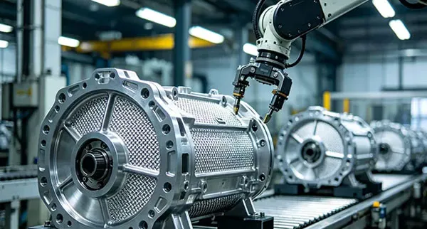
Injection molding part design should position gates so feedstock fills critical regions with balanced flow, manageable pressure, controlled knit lines, and an acceptable gate witness while avoiding flow-driven defects or distortion.
The gate is where feedstock enters the cavity, so its location influences how flow fronts travel through the part. A gate into a thick region may fill robustly but leave a witness on an important surface. A gate into a thin arm may freeze early or demand high pressure. Multiple gates can shorten flow length but create weld lines where fronts meet.
Weld or knit lines can matter if they occur at a highly stressed section, a sealing edge, a cosmetic area, or a location where powder/binder separation is more likely. Mold-flow analysis can help identify fill imbalance, air traps, pressure gradients, and gate options before steel is cut. Simulation does not eliminate trials, but it can reduce avoidable tool changes.
Vent locations are connected to gate design. Air must leave the cavity as feedstock enters. Trapped gas can cause burns, short shots, poor surface, or inconsistent fill. Very thin vents must control flash while remaining effective over production cycles, so tool maintenance becomes part of the process plan.
Gate removal also matters. If the gate is automatically separated, the witness geometry should not damage the part. If it requires a secondary trim or machining step, that labor belongs in total cost. A gate near a critical dimension can distort that area during removal. A gate on a hidden nonfunctional surface is often preferable if flow performance remains acceptable.
When comparing MIM with machining or conventional powder metallurgy, the freedom to mold complex flow-connected geometry is one of the key reasons to select metal injection molding. That freedom should be used to simplify the finished component, not to create avoidable tool actions or flow problems.
Injection molding part design should mold holes, threads, ribs, bosses, teeth, flats, and other features when they can be formed robustly, but it should leave secondary machining for features whose orientation, tolerance, surface, or tool risk makes molding uneconomical.
Holes parallel to the main mold-opening direction are usually easier than cross holes. A cross hole may require a side core or be drilled after sintering. The decision should compare annual volume, hole tolerance, tool complexity, cycle time, and secondary-operation cost. A high-volume hole can justify a side action; a low-volume precision hole may be cheaper to machine.
Threads can sometimes be molded, especially when the tool can use an unscrewing mechanism or when the thread orientation supports simple release. However, thread gauge, surface, flash, shrinkage, and tool wear need attention. A critical sealing or high-preload thread may still benefit from tapping or chasing after sintering.
Ribs should add stiffness without creating thick intersections. A rib that meets a wall can create local mass and differential shrinkage. Fillets at the rib root reduce stress concentration and improve flow. Bosses for screws, pins, or pivots should have enough surrounding support to avoid cracking during assembly.
Small logos, text, knurls, serrations, and texture can often be molded at low incremental piece cost once the tool is built. These features are valuable when they eliminate laser marking, stamping, or assembly orientation aids. However, extremely fine details increase tool-making and maintenance demands and may be affected by coating or polishing.
Functional surfaces should be classified by whether they can remain as-sintered. If a bore needs high roundness and a tightly controlled fit, sizing, reaming, grinding, or honing may be required. If a sealing face needs very low roughness and flatness, grinding may be more robust than demanding the entire part meet that finish. The right design uses MIM for geometry and places precision finishing only where function requires it.
Injection molding part design should use capability-based tolerances that distinguish critical functional dimensions from general geometry, because excessively tight blanket tolerances add tooling iteration, inspection, fixtures, and secondary machining without improving function.
The tolerance strategy should begin with the assembly. Identify dimensions that control fit, preload, gear mesh, sealing, concentricity, alignment, travel, electrical gap, or safety. Then identify reference datums that reflect how the part functions. Geometric dimensioning and tolerancing can be more useful than independent plus/minus dimensions because it communicates relationships.
MIM can provide good dimensional control, but shrinkage and distortion make the capability feature-dependent. A short dimension between two features in the same local mass may be more stable than a long dimension across an asymmetric part. Hole location relative to a molded datum may be easier than tight absolute dimensions across a free span.
For example, a 20.00 mm dimension with ±0.10 mm creates a total allowed band of 0.20 mm. If that tolerance is truly required for assembly, the supplier can plan tooling compensation and inspection around it. If the assembly actually tolerates ±0.25 mm, forcing ±0.10 mm can create unnecessary sorting or machining. Tolerance relaxation is one of the most direct ways to reduce MIM cost.
| Feature | Prefer As-Molded / As-Sintered When | Consider Secondary Operation When | Design Question |
|---|---|---|---|
| General outer profile | Normal form tolerance meets assembly | Very tight flatness or datum requirement | Does this surface locate or only provide clearance? |
| Bore | Fit is forgiving and geometry is stable | Tight diameter, roundness, bearing or sealing function | Can sizing, reaming or grinding add value only here? |
| Thread | Tooling can form it robustly and gauge requirement is moderate | High preload, sealing, very tight gauge or difficult orientation | Is molded thread cheaper than tapping at annual volume? |
| Cross hole | Side action is justified by volume and tool design | Low volume or tight positional tolerance | Does the side core reduce total cost? |
| Sealing face | As-sintered texture and flatness are acceptable | Leak-tight, low roughness or tight flatness | Should the design reserve grind stock? |
| Cosmetic surface | Mold texture or tumble finish is acceptable | Mirror finish or controlled directional appearance | Where can gates, ejectors and parting lines be hidden? |
Inspection should follow the same prioritization. Critical features may need CMM, functional gauges, optical measurement, surface roughness, hardness, or other methods. Noncritical dimensions can use sampling or simpler gauges. A drawing overloaded with inspection notes can slow production without increasing quality if the notes are not tied to risk.
An injection molding part design review before tooling should confirm function, material, wall distribution, tool access, gates, ejection, shrinkage strategy, tolerances, secondary operations, inspection, annual volume, and validation requirements.
Start with function. What loads, temperature, corrosion, wear, fatigue, impact, or magnetic behavior must the part survive? What are the mating components? Which failure mode is unacceptable? If the supplier does not understand the function, design-for-manufacture recommendations can accidentally weaken the application.
Next review geometry. Highlight undercuts, cross holes, internal threads, thin walls, thick masses, long unsupported spans, sharp internal corners, precision bores, sealing faces, and cosmetic surfaces. Decide which features should be molded and which should be finished later.
Then review the manufacturing route. Confirm the target material and heat treatment, gate strategy, parting line, ejection, debinding support, sintering orientation, setter concept, shrink compensation, machining, coating, marking, cleaning, and packaging. Any operation that can alter dimensions should be placed before final inspection.
Review the drawing for tolerance realism. Separate key characteristics from noncritical dimensions. Identify datums that can be inspected repeatedly. Define surface finish only where function needs it. If the component will be coated, specify whether dimensions apply before or after coating.
Finally, review commercialization. Provide annual volume, expected program life, prototype quantity, sample schedule, PPAP or first-article requirements, capability expectations, traceability, packaging, and change-control rules. Tooling choices depend heavily on volume. Industry MIM guidance commonly describes an economic range from several thousand parts per year to millions of parts for appropriate designs, illustrating why the production forecast matters during tool planning.
Hengji’s injection molding process and MIM pages provide the manufacturing context, but a customer-specific DFM review is the step that converts general process capability into a production plan. Sending both 3D and 2D data allows the engineer to assess geometry while preserving dimensional and quality requirements.
These FAQs answer common design questions about MIM wall thickness, shrinkage, draft, threads, tolerances, undercuts, and design-for-manufacture review.
No. The MIM supplier normally applies tool scale and local compensation using its feedstock, material, furnace, and process data. The customer should provide the final desired dimensions and clearly identify critical features.
Uniform walls are preferred because they simplify filling, debinding, heating, and shrinkage. Variations are possible, but abrupt thick-to-thin transitions and isolated heavy masses should be reviewed for flow, debinding time, and distortion risk.
Yes, when slides, lifters, cores, or other tooling actions are economically justified. For some cross holes or undercuts, secondary machining is simpler. The decision should compare tool cost, annual volume, tolerance, and cycle time.
Many thread forms can be molded if tool access and shrink control are suitable. High-precision, sealing, high-preload, or awkwardly oriented threads may still require tapping, chasing, or machining after sintering.
There is no single tolerance that applies to every feature. Capability depends on part size, geometry, material, shrink path, tool, datum structure, and secondary operations. Tight tolerances should be reserved for functionally critical dimensions and confirmed with the supplier.
Send a 3D model, controlled 2D drawing, material and finish requirements, annual volume, mating-component information, functional loads, environment, critical dimensions, inspection requirements, and any current quality or validation standard.
Effective injection molding part design for MIM reduces risk by making the geometry compatible with mold filling, ejection, debinding, sintering shrinkage, dimensional control, finishing, and production economics before tooling is committed.
The most successful MIM components are not simply “complex.” They are complex in ways the process can form repeatedly. Uniform mass, sensible draft, deliberate gate and parting-line locations, manufacturable holes and threads, realistic tolerances, clear datums, and selective secondary machining create a stable process window.
For buyers, a DFM review should happen before a supplier is selected solely on price. The lowest quoted tooling or piece price can become expensive if the drawing creates chronic distortion, fragile tool inserts, repeated sorting, or unnecessary machining. A transparent review that explains what will be molded, what will be finished, and how critical features will be inspected is a better predictor of production success.
For Hengji projects, the best starting package is the 3D model, 2D drawing, material target, annual volume, mating-part information, operating environment, and critical quality requirements. That gives the engineering team enough context to evaluate whether MIM is the right process and where small geometry changes can improve manufacturability without compromising function.