What are you looking for?
Powder metal gears are widely used in automotive mechanisms because the powder metallurgy process can form teeth, hubs, splines, keyways, bosses, and multi-level features in a near-net-shape production route. The opportunity is larger than replacing a machined gear with a less expensive copy. When the component is designed around powder compaction and sintering, the process can reduce material loss, combine functions, stabilize high-volume production, and minimize secondary machining.
The automotive market remains central to the powder metallurgy industry. In its 2025 State of the PM Industry report, the Metal Powder Industries Federation stated that more than 70% of North American iron-powder shipments were destined for passenger vehicles. The same report estimated that the average North American passenger vehicle contained approximately 14.8 kg, or 32.7 lb, of PM components in 2024. These figures include more than gears, but they demonstrate the depth of PM adoption in vehicle systems.
This guide focuses on the decisions that determine whether a powder metal gear will perform reliably: application load, tooth geometry, density distribution, material, heat treatment, lubrication, dimensional control, noise and vibration, validation, and supplier capability. It is written for automotive engineers, transmission and actuator designers, sourcing teams, and quality professionals evaluating a new or transferred program.
Hengji manufactures powder metallurgy components for automotive and industrial applications. The brand's role in a gear project is not limited to producing a drawing. Early engineering review can identify where the geometry is naturally compatible with pressing, where performance requires densification or heat treatment, and where a small design change can remove a costly operation.
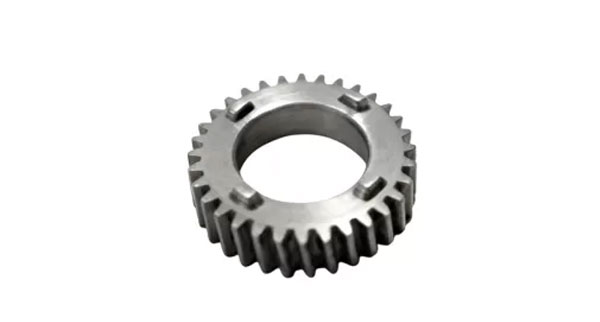
Powder metal gears are toothed components formed by compacting engineered metal powder in a precision die, sintering the green compact, and applying only the finishing operations needed for the application.
In the conventional press-and-sinter route, powder is blended to achieve the required chemistry and pressing behavior. A controlled quantity fills a die cavity. Upper and lower punches compact the powder under high pressure, forming a green gear that already contains most of its final geometry. The gear is then heated in a controlled-atmosphere furnace below the melting point of the base metal, allowing particles to bond through diffusion.
Gear teeth can often be formed directly in the tooling. Depending on the design, the process may also form an integral hub, web, flange, bore, spline, keyway, timing feature, or axial projection. Sizing or coining can improve selected dimensions after sintering. Heat treatment, steam treatment, shot peening, machining, grinding, impregnation, coating, and other secondary operations are added only when the functional requirements justify them.
MPIF states that typical powder metallurgy manufacturing can use more than 97% of the starting raw material in the finished part. This high utilization is valuable for recurring automotive volumes because the process avoids much of the chip generation associated with cutting gear teeth and turning the full component from bar or forged stock.
Automotive gear applications suit powder metallurgy when recurring volume, pressable geometry, functional material properties, and near-net-shape feature integration create a stable total-cost advantage.
Automotive systems contain many gears that transmit moderate torque, position an actuator, drive a pump, synchronize motion, move a seat or window, engage a clutch mechanism, or transfer power in an auxiliary subsystem. Not every gear requires the same material density, tooth accuracy, fatigue strength, or surface finish as the highest-loaded transmission gear. Powder metallurgy creates value by matching the material and process route to the real duty cycle.
The process is particularly effective for high-volume parts because one compaction stroke can form the tooth profile and several additional features. Compared with machining, PM can reduce cutting time, workholding, tool changes, chips, and dimensional variation between separate operations. Compared with a multi-piece assembly, PM may consolidate components and remove fasteners or joints.
Powder metallurgy can also provide application-specific structures. Controlled porosity can retain lubricant. Material systems can be selected for wear, strength, hardenability, magnetic properties, or dimensional stability. Localized densification and targeted finishing can be applied to the features that carry the highest load rather than making the entire component more expensive.
The business case is strongest when the engineering team evaluates annual volume, program duration, tool investment, part mass, eliminated operations, scrap, inspection, packaging, and warranty risk together. A lower quoted unit price has little value if tooth life, noise, or process capability is not validated.
The choice among powder metal, machined, and forged gears depends on load, geometry, volume, accuracy, material properties, finishing requirements, and the value of near-net-shape production.
| Factor | Powder Metal Gear | Machined Gear | Forged and Machined Gear |
|---|---|---|---|
| Best economic range | Recurring medium-to-high volume with pressable geometry | Prototype, low volume, large sizes, or highly flexible revisions | High-load applications where wrought flow and subsequent machining are justified |
| Material utilization | Commonly very high; MPIF cites more than 97% starting-material use for PM | Lower when significant stock is removed as chips | Better than full machining in some cases, but flash and machining allowance remain |
| Feature integration | Teeth, hub, bore, web, keyway, spline, and levels can be formed together | Highly flexible but may require several cutting setups | Near-net blank followed by machining; complex small details still require finishing |
| Density | Application-specific; standard PM retains porosity, with densification options available | Wrought-stock density | Wrought density with favorable grain flow when properly designed |
| Tool investment | Dedicated compaction and sizing tools | Lower dedicated forming-tool cost, but higher cycle cost | High forging-die investment plus machining fixtures and cutters |
| Design changes | Most economical before tooling release; later geometry changes can be costly | Relatively flexible through programs and fixtures | Changes may affect both forging and machining systems |
| Typical decision | Choose when required performance can be achieved with near-net-shape efficiency | Choose for flexibility, low volume, or features unsuited to pressing | Choose for severe load cases that justify the added process chain |
Powder metal should not be selected solely because the gear looks simple, and machining should not be retained solely because it was used for the prototype. The correct comparison starts with tooth-root stress, contact stress, impact loading, duty cycle, lubrication, operating temperature, alignment, required life, and acceptable noise. The production route is chosen after the performance envelope is understood.
A reliable powder metal gear design directs load through adequately supported teeth, roots, webs, hubs, and interfaces without creating local stress concentrations or unstable compaction zones.
The gear tooth is only one part of the load path. Torque enters through a bore, spline, keyway, press fit, pin, clutch feature, or integral shaft connection. It travels through the hub and web before reaching the teeth. A robust design considers every transition. A strong tooth profile cannot compensate for a thin web, a sharp hub corner, an insufficient press fit, or a keyway that creates a severe notch.
Begin by defining maximum and continuous torque, overload events, reversal, shock, start-stop frequency, speed, expected life, temperature, and lubrication. Separate static strength from fatigue. A parking mechanism may experience infrequent high load; an actuator gear may experience many low-load cycles; a pump gear may experience continuous contact and fluid interaction.
Tooth-root fillet radius is important because sharp transitions increase bending stress and are difficult to fill uniformly. Adequate rim thickness supports the teeth and limits deformation. Hub length and wall thickness influence compaction density and press-fit behavior. Chamfers can improve assembly but should be designed so they are toolable and do not remove too much load-bearing area.
Draft is usually not required on the straight gear teeth in the same manner as injection molding, but the part must eject without damaging the green compact or tooling. Features that trap the part or require radial tool movement should be redesigned or machined. The engineering team should identify the pressing direction on the drawing and review every feature relative to that axis.
Density distribution describes how uniformly the compacted powder reaches the intended density throughout the tooth, rim, web, hub, and multi-level features.
Density strongly influences strength, hardness response, dimensional change, fatigue, and wear. A nominal average density can hide local low-density regions. Tall hubs, thin flanges, abrupt changes in section, deep counterbores, and complex multi-level geometries can create uneven powder fill or compaction ratios. The supplier must design powder transfer, punch motion, tool levels, and pressing sequence to manage those risks.
For a gear, local density at the tooth root and loaded flank may be more important than an average value measured from the entire component. When performance is demanding, the validation plan can include sectioned density measurements, metallographic evaluation, hardness traverses, or other methods agreed by the customer and supplier.
Increasing density usually improves many mechanical properties, but it also increases compaction force, tool stress, ejection force, and cost. The goal is not maximum density everywhere. The goal is sufficient and stable density in the regions that control performance. Selective densification, double pressing and sintering, warm compaction, surface rolling, or powder forging may be considered when standard press-and-sinter properties are insufficient.
A powder metal gear material is selected by matching composition, density, heat treatment, hardness, toughness, wear, dimensional response, and cost to the application.
Iron-copper-carbon and iron-nickel-copper-molybdenum systems are common examples of ferrous PM material families, but the appropriate grade depends on the required strength and hardenability. Pre-alloyed, diffusion-alloyed, and admixed powders offer different combinations of compressibility, chemistry distribution, dimensional change, and heat-treatment response.
Carbon content influences hardness and strength after sintering or heat treatment. Copper can improve strength and affects dimensional change. Nickel and molybdenum can improve hardenability and mechanical performance, but alloy cost and processing behavior must be considered. The material designation should be tied to a recognized standard or a clearly defined supplier specification with density, chemistry, hardness, and mechanical-property requirements.
For corrosive environments or special magnetic behavior, stainless and soft-magnetic PM systems may be appropriate. For an oil-pump or actuator component, fluid compatibility and dimensional stability can be as important as tooth strength. For a clutch mechanism, impact, wear, and engagement behavior may dominate.
Do not copy a wrought-steel grade onto a PM drawing without discussing the functional requirement. Powder metallurgy uses material systems and density levels that may not map one-to-one to bar-stock grades. Communicate the needed performance, and allow the PM engineering team to propose a material route that can be manufactured consistently.
Heat treatment and surface engineering modify hardness, wear resistance, fatigue behavior, friction, corrosion response, or dimensional stability after sintering.
Sinter hardening can combine sintering and accelerated cooling to create a hardened microstructure without a separate conventional heat-treatment cycle. Secondary carburizing, carbonitriding, induction hardening, through hardening, tempering, steam treatment, shot peening, and surface densification may also be used depending on material and application.
The treatment must be selected with porosity in mind. Open pores influence furnace atmosphere, quench response, oil retention, plating, and corrosion. Heat treatment can also cause distortion or dimensional change. Critical bores, runout, tooth alignment, and press-fit dimensions should be reviewed after the full process chain, not only after sintering.
Surface rolling or local densification can improve the loaded tooth flank and root while preserving near-net-shape economics in the rest of the gear. Shot peening may introduce compressive residual stress and improve fatigue performance when properly controlled. Steam treatment can create an oxide layer that may improve wear and corrosion behavior in selected applications, though it is not a universal substitute for a dedicated corrosion coating.
Every surface process should have measurable acceptance criteria. Avoid vague notes such as “harden as required.” Specify the material condition, hardness range and location, case depth where applicable, allowable decarburization, surface finish, distortion limits, and testing frequency.
Gear accuracy describes how closely tooth profile, lead, pitch, runout, and spacing match the intended geometry and how those variations affect transmission error, contact, vibration, and noise.
A gear can meet basic dimensions and still create unacceptable noise if tooth-to-tooth variation, eccentricity, lead error, or profile error is excessive. The required accuracy should be linked to the application. A low-speed seat-adjustment gear has different noise and load expectations from an electric pump gear or a high-speed actuator.
Powder compaction tooling forms the tooth geometry, so tool accuracy, elastic deflection, wear, powder fill, sintering change, and sizing all influence the finished gear. Runout can originate from the relationship between the bore and teeth, from density variation, or from post-sintering handling. The supplier should define the datum system and use a measurement method that reflects the functional assembly.
ANSI/AGMA 6008-B24, Specifications for Powder Metallurgy Gears, describes information that purchasers and PM gear manufacturers should agree upon. Buyers should use the current standard and related engineering methods rather than relying on a generic “AGMA quality” note with no specified measurement scope. The applicable grade, inspection parameters, sampling, and reporting must be defined for the program.
Noise, vibration, and harshness are system outcomes. Housing stiffness, shaft alignment, bearing clearance, center distance, backlash, motor torque ripple, lubrication, and mating-gear quality can all affect sound. When an NVH problem appears, do not assume the powder metal gear is the only source. Use contact-pattern analysis, runout data, single-flank or double-flank testing where appropriate, and assembly-level testing to isolate the cause.
Powder metal gear failure occurs when tooth stress, contact conditions, material state, geometry, lubrication, alignment, or manufacturing variation exceeds the validated design window.
Repeated load initiates a crack near the root where bending stress is highest. Risk increases with sharp fillets, low local density, insufficient rim support, overload, misalignment, or an unsuitable material condition. Countermeasures include profile review, larger root radius, improved density, stronger material, heat treatment, shot peening, and reduced system load.
Repeated Hertzian contact stress can create pits on the tooth flank. Surface density, hardness, finish, lubrication, load distribution, and contamination all matter. Surface densification or a different heat-treatment route may be required for demanding contact conditions.
Insufficient lubricant film, poor material pairing, high sliding, rough surfaces, excessive temperature, or contamination can accelerate wear. Analyze lubricant viscosity, supply method, operating temperature, surface finish, hardness difference, and mating material.
Sudden shock, foreign-object entry, assembly impact, brittle microstructure, or insufficient toughness can break a tooth. Review overload events, engagement timing, material toughness, heat-treatment condition, and handling controls.
An excessive interference fit, thin hub wall, sharp keyway, or density variation can create radial stress and cracking. Press-fit calculations should use the actual PM material condition and porosity, not assumptions taken directly from wrought steel.
Pitch variation, runout, incorrect backlash, housing distortion, bearing clearance, or mating-gear mismatch can create noise before physical failure. Dimensional and functional testing should be correlated with assembly sound measurements.
Failure analysis should preserve evidence. Record lot, mileage or cycles, operating conditions, lubricant state, fracture location, hardness, density, microstructure, dimensional data, and mating-part condition. A supplier can respond more effectively when returned parts are accompanied by system information rather than only a photograph.
Clutch and sector gear applications require different design priorities because engagement impact, partial-tooth loading, motion range, and torque direction vary by mechanism.
A clutch gear may experience repeated engagement, impact, sliding, and localized contact. Tooth-edge condition, chamfer, hardness, backlash, and engagement timing can influence wear and noise. If the gear carries a dog-clutch feature or other engagement geometry, the full interaction with the mating part should be reviewed.
Sector gears use only a portion of a full gear circumference and are common in actuators, adjustment mechanisms, locks, throttle systems, and position-control assemblies. Their incomplete rim creates asymmetric mass and can affect compaction, ejection, sintering support, and measurement. The start and end teeth may also experience different load conditions from the middle teeth.
When evaluating automotive gears, provide the manufacturer with the motion range, maximum torque, stop position, load direction, backlash, mating gear, shaft support, lubrication, operating temperature, and life-cycle profile. These details help determine whether standard PM density is sufficient or whether material, heat treatment, sizing, or local finishing should be upgraded.
A gear validation plan links drawing characteristics and material controls to functional tests that represent production variation and real operating conditions.
Validation should begin with dimensional and material confirmation but must not end there. A complete plan may include:
Full dimensional layout against the released drawing and datum scheme.
Gear profile, lead, pitch, runout, and tooth-thickness measurements as applicable.
Density testing at agreed locations, including local sections for critical designs.
Chemistry, hardness, microstructure, case depth, and heat-treatment verification.
Surface finish and coating or treatment verification.
Torque-to-failure, bending fatigue, contact fatigue, or wear testing.
Press-fit, push-out, or spline torque testing for the hub interface.
Endurance testing in the actual actuator, pump, clutch, or transmission subassembly.
Noise and vibration testing at defined speed, torque, temperature, and lubrication conditions.
Environmental tests for corrosion, temperature cycling, contamination, or fluid compatibility.
Sample selection should represent more than the best parts from one short run. Include multiple cavities or tools where applicable, different furnace positions, separate production lots, and normal material variation. For an automotive launch, the customer may require PPAP documentation, capability studies, measurement-system analysis, material certificates, process flow, PFMEA, control plan, and submission samples.
Acceptance criteria must be established before testing. “No abnormal noise” is difficult to enforce without a sound level, frequency band, reference unit, test fixture, operating point, and evaluation method. “No visible wear” is similarly vague without a cycle count and inspection standard.
A supplier audit verifies that the manufacturer has the engineering, tooling, production, quality, traceability, and capacity systems needed to sustain the program after approval.
| Audit Area | Evidence to Request | Risk if Missing |
|---|---|---|
| Design engineering | DFM review, pressing-direction analysis, material proposal, tolerance discussion, simulation or prior similar experience | Tooling is released around an unstable or unnecessarily expensive design |
| Powder control | Approved suppliers, incoming inspection, lot traceability, storage, blend control, contamination prevention | Chemistry, fill, density, and dimensional variation |
| Tooling capability | Internal or qualified toolmaking, maintenance history, spare strategy, wear criteria, revision control | Long downtime, tooth-profile drift, inconsistent replacement tooling |
| Compaction process | Press capacity, fill control, force monitoring, setup standards, green-part handling | Density gradients, cracks, lamination, dimensional instability |
| Sintering | Furnace calibration, atmosphere monitoring, belt loading rules, temperature records, contingency capacity | Variable microstructure, hardness, carbon, dimensions, or oxidation |
| Gear measurement | Calibrated gear inspection equipment, methods, master gears where used, gauge R&R | Parts pass a generic check but fail functional meshing or NVH targets |
| Special processes | Heat-treatment approvals, coating controls, audits, certificates, incoming verification | Outsourced variation is not detected before shipment |
| Automotive quality | APQP/PPAP experience, PFMEA, control plan, capability, traceability, corrective action | Launch delay and slow containment when issues arise |
| Capacity and continuity | OEE or capacity model, backup equipment, spare furnace capacity, disaster plan, key-person coverage | Supply interruption after demand ramps |
Hengji reports that its first-process qualification rate improved from 98.45% to 99.31% after implementing an integrated quality-management model. Buyers should treat this as company-reported performance and verify project-specific evidence, including capability data, inspection records, traceability, response time, and validation results for the actual gear family.
A strong RFQ describes the gear, its duty cycle, critical characteristics, validation expectations, and commercial forecast clearly enough for the supplier to design a reliable process.
Release controlled technical data. Send a 2D drawing, 3D model, revision history, gear data, datum system, and applicable standards.
Describe the application. State mating gear, center distance, shaft and bearing arrangement, lubricant, temperature, speed, torque, shock, reversal, and intended life.
Identify critical characteristics. Mark tooth measurements, runout, bore, perpendicularity, hardness, density, surface finish, and interface requirements that control function.
Provide volume information. Include prototype quantity, annual volume, monthly peak, program duration, ramp schedule, and service demand.
Define quality deliverables. Specify PPAP level, capability targets, certificates, traceability, test reports, packaging, and change-notification rules.
Ask for a process breakdown. Request tooling concept, material, density, sintering, sizing, heat treatment, machining, finishing, and inspection sequence.
Separate commercial items. List tooling, gauges, fixtures, samples, validation, piece price, optional operations, and amortization independently.
Invite the supplier to challenge the drawing before quotation. A feature added for machining convenience may be unnecessary in PM. A tight tolerance may have no functional value. A radial hole may be repositioned to eliminate a secondary operation. A hub may be adjusted to improve density and reduce tool stress. These changes are cheapest before tooling is approved.
Powder metallurgy can create economic value across internal gears, pump elements, actuators, and auxiliary drives when geometry and performance are matched to the process.
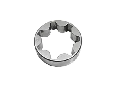
Internal gears are attractive because cutting internal teeth can require specialized tooling and longer machining cycles. Powder compaction can form the internal profile directly when the geometry supports tool entry and ejection. The design must still address tooth-root strength, hub or rim support, dimensional change, and measurement access.
Pump gears and gerotors require close attention to profile accuracy, clearance, surface condition, density, and fluid compatibility. Their performance may be evaluated through flow, pressure, efficiency, leakage, noise, and endurance rather than only static dimensions. Near-net-shape production can be valuable, but the validation must reflect the actual hydraulic system.
Actuator gears often combine teeth with a cam, stop, indicator, spring feature, or shaft interface. This functional integration is a core advantage of powder metal gears. Consolidation can reduce assembly count and tolerance stack-up, but the integrated component must be evaluated for combined loading and manufacturing variation.
Electric-vehicle growth changes the mix of PM opportunities rather than eliminating them. Some traditional internal-combustion applications decline, while seat systems, closures, thermal-management pumps, e-axle auxiliaries, braking actuators, steering systems, fluid systems, and other mechanisms continue to require compact metal components. Suppliers should demonstrate application knowledge rather than relying on a generic automotive claim.
These frequently asked questions summarize the purchasing and engineering issues most often raised during powder metal gear development.
Yes, when material, density, geometry, heat treatment, lubrication, and validation match the load case. PM gears are used in many automotive mechanisms, but not every gear is suitable for a standard press-and-sinter route. High-load applications may require densification, advanced material systems, surface treatment, or another manufacturing process.
The main advantage is forming teeth and additional features near net shape at recurring volume. MPIF reports that PM typically uses more than 97% of the starting raw material. Savings can also come from fewer machining setups, reduced scrap, part consolidation, and stable high-volume cycles.
Powder metal gears can be specified and inspected using relevant AGMA guidance, including ANSI/AGMA 6008-B24. The purchaser and supplier must agree on gear data, accuracy requirements, measurement methods, material condition, and acceptance criteria. A vague “AGMA quality” note is not sufficient.
Not always. Low or moderate-load gears may perform in the as-sintered condition. Higher wear, fatigue, or impact requirements may justify sinter hardening, carburizing, carbonitriding, induction hardening, shot peening, or surface densification. The full process should be validated for dimensional change and performance.
Possible causes include pitch or profile variation, runout, incorrect backlash, tooth contact, surface finish, mating-gear error, shaft misalignment, bearing clearance, housing stiffness, motor excitation, and lubrication. Assembly-level testing is needed because noise is a system result, not only a gear-material issue.
Send the 2D drawing, 3D model, gear data, material or performance requirements, torque and speed, duty cycle, lubricant, mating-part information, annual volume, program life, quality documentation, validation needs, and delivery schedule. Hengji can then review pressability, tooling, material, density, heat treatment, and secondary operations.
A successful powder metal gear program is created when component design, material, tooling, sintering, finishing, inspection, and application validation are developed as one system.
Powder metal gears can provide strong automotive value through high material utilization, near-net-shape tooth formation, feature integration, and repeatable volume production. The process is not a shortcut around engineering. Tooth-root load, contact stress, density distribution, heat treatment, runout, noise, lubrication, and assembly conditions must all be addressed.
The best time to improve a PM gear is before the drawing and tooling are frozen. Work with a supplier that can explain pressing direction, local density, material selection, tool construction, furnace control, gear inspection, failure analysis, and automotive validation. Hengji can review a new design or an existing machined component and identify where powder metallurgy may reduce total cost without compromising the required function.
These authoritative industry sources provide additional data and specification guidance for powder metallurgy and PM gears.