What are you looking for?
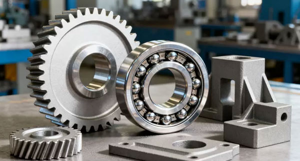
The powder metallurgy process gives engineers a practical route to manufacture repeatable metal components with limited scrap, controlled material properties, and fewer machining operations. It is especially valuable when a part must be produced in substantial volumes, has a shape that can be formed in a rigid die, and benefits from near-net-shape manufacturing. Automotive gears, pump components, cams, structural parts, sensor-related components, bearings, and appliance mechanisms are common examples, but the process decision should always begin with the drawing, load case, material target, annual volume, and inspection requirements.
This guide explains how conventional press-and-sinter powder metallurgy works, what each manufacturing stage controls, where design errors occur, and how buyers can compare PM with machining, casting, forging, and metal injection molding. It is written for product engineers, sourcing teams, quality managers, and manufacturers that need a technical basis for discussing a new component rather than a simplified definition of the process.
According to the Metal Powder Industries Federation, conventional PM can place more than 97% of the starting raw material into the finished component. The same industry source explains that rigid-die compaction can reach pressures up to approximately 50 tons per square inch. These figures demonstrate why PM is attractive for material-efficient, high-volume manufacturing, but they do not mean every geometry or alloy is automatically economical. Tool access, density distribution, sintering behavior, secondary operations, and quality documentation still determine the final result.
The powder metallurgy process is a manufacturing sequence that forms metal powder into a compacted shape and then sinters it below the material's melting point to create a functional metal component. Conventional press-and-sinter PM normally includes powder selection, blending, die compaction, sintering, optional secondary operations, and final inspection. The process differs from casting because the material is not fully melted and poured, and it differs from machining because the primary geometry is created by compacting powder rather than removing material from a solid block.
The process starts with a material system rather than only a nominal alloy name. Particle size distribution, particle shape, apparent density, flow behavior, lubricant content, and alloying method affect how the powder fills the tool and how the compact behaves during pressing and sintering. A material that produces acceptable laboratory properties may still be difficult to run consistently if it does not fill a multi-level die uniformly or if it causes excessive tool wear.
After powder is metered into the die, upper and lower punches apply pressure. The particles rearrange, deform, and mechanically interlock to produce a “green compact.” The green part has enough strength for handling, but it does not yet have the metallurgical bonding required for service. Sintering then heats the component in a controlled atmosphere, allowing diffusion and bonding between particles. Depending on the part specification, sizing, heat treatment, steam treatment, oil impregnation, machining, grinding, plating, coating, or assembly may follow.
A reliable powder metallurgy process therefore depends on much more than a press and furnace. Tool design, powder control, furnace atmosphere, process monitoring, dimensional compensation, and inspection planning must work as one system.
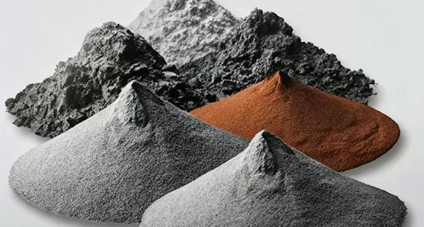
Powder selection and blending define the chemical composition, flow behavior, compressibility, lubrication, and eventual performance of a powder metallurgy part. Engineers should not choose powder solely by comparing tensile strength values in a general material table. The alloy must be evaluated in relation to density, section thickness, heat treatment, porosity, corrosion environment, magnetic behavior, wear, fatigue, and the specific manufacturing route.
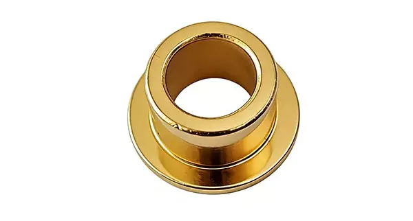
Iron-based powders are widely used for structural components because they offer a broad balance of cost, strength, machinability, and heat-treatment response. Stainless steel powders can support corrosion resistance and elevated-temperature applications, while copper, bronze, and other nonferrous systems are used for bearings, filters, electrical components, and specialized mechanisms. Soft magnetic materials require additional attention to chemistry, density, heat treatment, and magnetic loss. The most appropriate choice is the material system that meets functional requirements with a stable process window, not necessarily the strongest alloy listed.
Particle size distribution: Influences flow, packing, surface area, sintering response, and final porosity.
Particle shape: Irregular particles may interlock effectively during compaction, while more spherical powders can improve flow but behave differently under pressure.
Apparent density: Affects how much powder must fill the die and how the fill height is managed.
Flow rate: Important for consistent high-speed die filling, especially in thin or multi-level geometries.
Compressibility: Determines the density that can be achieved at a given pressure.
Lubrication: Reduces friction during compaction and ejection but must be controlled because excessive lubricant can influence density and sintering.
Alloying method: Prealloyed, diffusion-alloyed, admixed, or hybrid systems can produce different combinations of compressibility and final properties.
Blending must distribute alloying additions and lubricant uniformly. Segregation can create local differences in chemistry, dimensional change, hardness, or strength. For that reason, powder receiving controls, lot identification, storage humidity, mixing time, blender loading, transfer methods, and line clearance should be part of the control plan. A buyer evaluating a PM supplier should ask how powder lots are identified, how blends are protected from contamination, and whether material substitutions require formal approval.
Powder compaction forms a rigid green component by pressing a controlled mass of metal powder inside a precision die. The objective is not simply to achieve the highest possible pressure. The objective is to create the required shape with sufficiently uniform density, adequate green strength, safe ejection, and manageable tool stress.
Hengji's current technology information describes a typical compaction range of approximately 100 to 800 MPa, while MPIF explains that conventional presses can operate at pressures up to about 50 tons per square inch. The exact pressure depends on the alloy, lubricant, part geometry, projected area, required density, press capability, and tooling design. A large projected area may require substantial total press force even when nominal pressure is moderate.
Friction between powder and the die wall causes density gradients. Long, thin parts, abrupt level changes, deep hubs, narrow webs, and large differences in section thickness can be difficult to compact uniformly. A low-density zone may shrink differently during sintering or become a fatigue weakness, while an over-dense zone can increase ejection force and tool loading. Multi-action tooling, floating dies, carefully sequenced punches, and optimized fill can improve the density profile.
Designers should understand that conventional rigid-die PM has a primary pressing direction. Features perpendicular to that direction, such as undercuts, certain cross holes, reverse tapers, and enclosed side details, may require secondary machining or a different process. A part that looks easy in a 3D model may be expensive or impossible to eject from a conventional tool.
The green compact must survive ejection, handling, transport to the furnace, and placement on sintering fixtures. Thin walls, sharp corners, small projections, and poorly supported levels can crack before sintering. Ejection stress is affected by die-wall friction, compact length, density, lubrication, surface condition, and tool alignment. Small cracks can be difficult to see before sintering and may become obvious only after heat treatment or functional testing.
For new programs, the supplier should conduct a design-for-manufacturability review before finalizing tooling. That review should identify pressing direction, punch count, die split, fill ratio, risk of density variation, ejection direction, fragile green features, and likely secondary operations.
Powder metallurgy sintering heats the green compact in a controlled atmosphere so that metal particles bond by diffusion and the component develops its final microstructure and strength. Sintering is performed below the principal material's melting point, although a liquid phase may be deliberately created in some alloy systems to improve densification or bonding.
A typical furnace cycle includes preheating or lubricant removal, high-temperature sintering, and controlled cooling. Temperature, time, atmosphere composition, belt loading, part orientation, and cooling rate influence dimensional change, carbon content, oxide reduction, hardness, microstructure, and mechanical performance. Furnace atmosphere is not merely a protective gas; it participates in chemical control. Dew point, oxygen potential, carbon potential, gas flow, and furnace cleanliness can all affect the part.
Sintering creates bonding, but it does not automatically eliminate all porosity. Conventional press-and-sinter parts commonly retain controlled porosity, which can be beneficial for oil-impregnated bearings, filtration, weight reduction, or damping. For high-stress structural parts, density may be increased through warm compaction, double pressing and double sintering, sinter forging, surface densification, infiltration, or alternative PM routes. The correct approach depends on the load path and required properties.
Parts may grow or shrink during sintering depending on powder chemistry, compact density, alloying additions, lubricant, furnace conditions, and material interactions. Tool dimensions therefore include compensation based on validated process data. The compensation is not a universal percentage. A supplier must establish the relationship between tool size, green size, sintered size, secondary processing, and final measurement for the specific material and geometry.
Multi-level parts can distort if density is uneven or if support during sintering is inadequate. Thin rings may become out of round; asymmetric parts may warp; long components may bow; and features with different masses may heat and cool at different rates. Sintering fixtures, part orientation, belt loading, and cooling controls should be considered during process development.
Secondary operations modify the dimensions, surface, mechanical properties, porosity, or assembly condition of a sintered powder metallurgy part when the as-sintered result does not meet every requirement. PM should reduce unnecessary secondary work, but insisting on a “no secondary operation” design can be counterproductive when a simple sizing or machining step creates a more reliable and economical component.
| Secondary Operation | Primary Purpose | Typical Use | Design Consideration |
|---|---|---|---|
| Sizing or coining | Improve dimensional accuracy, roundness, flatness, or local density | Bores, diameters, gear features, bearing seats | Requires controlled material movement and tool access |
| Heat treatment | Increase hardness, wear resistance, or strength | Gears, cams, locking parts, structural components | Porosity affects atmosphere response and distortion |
| Steam treatment | Create an oxide layer that can improve sealing, corrosion behavior, and surface hardness in suitable ferrous parts | Pump components and selected structural parts | Not appropriate for every alloy or dimensional requirement |
| Oil impregnation | Fill connected porosity with lubricant | Self-lubricating bearings and bushings | Oil type, viscosity, operating temperature, and storage matter |
| Machining | Add cross holes, threads, undercuts, tight local tolerances, or sealing features | Complex interfaces and critical bores | Interrupted cuts and porosity affect tool selection |
| Grinding or honing | Achieve precise geometry or surface finish | Bearing surfaces, gear faces, sealing diameters | Should be applied only where function requires it |
| Plating or coating | Improve corrosion, friction, appearance, or wear performance | Automotive and industrial components | Porosity may require sealing or special preparation |
| Assembly | Integrate inserts, shafts, magnets, springs, or multiple PM pieces | Subassemblies and mechanisms | Press-fit stress and dimensional stack-up must be validated |
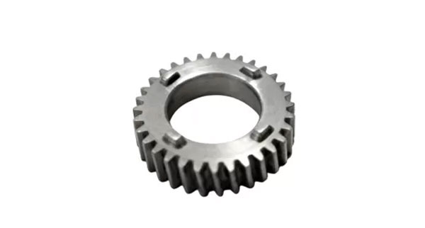
Each secondary operation adds cost, handling, inspection, and schedule risk. The engineering goal is to apply secondary work selectively to function-critical features. For example, a gear may be formed near net shape, sized for accuracy, heat treated for wear, and ground only on a critical datum. This is often more economical than machining the entire part from bar stock.
Powder metallurgy design guidelines align the component geometry with die filling, uniaxial compaction, ejection, sintering, and secondary operations. Early collaboration between the customer and PM manufacturer can remove cost before tooling is released and can prevent late changes caused by cracks, distortion, inconsistent density, or inaccessible features.
Features should be designed so the compact can be pressed and ejected along one primary axis. Steps and multiple levels are possible, but each level can require additional punches and more complex tooling. Side holes, undercuts, and reverse tapers should be evaluated for secondary machining or redesign.
Large changes in thickness can create uneven fill and density. Gradual transitions, generous radii, and balanced geometry help powder flow and reduce stress concentrations. The allowable geometry depends on material, size, and tooling concept, so generic wall-thickness rules should not replace supplier review.
Not every dimension needs the same tolerance. Critical interfaces should be identified, while nonfunctional dimensions should allow the natural capability of the PM process. Over-tolerancing increases sizing, machining, sorting, inspection, and scrap. A drawing should distinguish safety or performance-critical characteristics from reference or clearance dimensions.
Inspection becomes more reliable when the part has stable datum surfaces that can be located consistently. Irregular or porous surfaces, rounded edges, and inaccessible features can produce measurement variation. The measurement method should be agreed during development rather than after samples are made.
Thin punches, sharp corners, small teeth, and abrasive powders increase tool risk. A minor radius or geometry adjustment can significantly improve tool strength and maintenance. For high-volume programs, tooling robustness often matters more than producing the most visually compact design.
Powder metallurgy materials range from iron and stainless steel systems to bronze, copper, soft magnetic alloys, and specialized composites, with each material chosen for a specific combination of processability and performance. The table below is a selection framework rather than a substitute for a formal material specification.
| Material Family | Common Functional Needs | Typical PM Applications | Questions to Confirm |
|---|---|---|---|
| Iron and low-alloy steel | Strength, wear resistance, heat treatment, cost control | Gears, sprockets, cams, brackets, structural automotive parts | Density, carbon level, heat treatment, fatigue requirement |
| Stainless steel | Corrosion resistance, temperature resistance, clean appearance | Emission components, sensor parts, pump components, hardware | Grade, corrosion medium, passivation, magnetic behavior |
| Bronze and copper-based materials | Low friction, conductivity, corrosion resistance | Bearings, bushings, electrical components | Oil impregnation, load, speed, temperature, conductivity |
| Soft magnetic materials | Magnetic flux control, low loss, electromagnetic response | Motor, actuator, sensor, and solenoid components | Frequency, induction, coercivity, heat treatment, insulation |
| Infiltrated or high-density systems | Higher strength, pressure tightness, improved fatigue behavior | Highly loaded structural and hydraulic parts | Density target, leak requirement, cost of extra processing |
| Special composites | Tailored thermal, electrical, wear, or friction properties | Contacts, friction materials, filters, specialized tools | Material availability, test method, regulatory requirements |
Powder metallurgy should be selected when the geometry, material system, production volume, and performance requirements create a lower total manufacturing cost than competing processes. No process is universally superior. The best decision compares tooling, material utilization, cycle time, secondary work, dimensional capability, risk, and lifetime volume.
| Process | Best Fit | Advantages | Limitations |
|---|---|---|---|
| Conventional press-and-sinter PM | Medium to high volumes of parts compatible with uniaxial compaction | High material utilization, repeatability, integrated features, controlled porosity | Tool access limits, density gradients, retained porosity, tooling investment |
| CNC machining | Low volumes, prototypes, very tight local tolerances, geometries accessible to tools | Flexible revisions, broad material selection, no dedicated forming tool | Material removal, longer cycle time, rising unit cost at high volume |
| Casting | Larger or more three-dimensional shapes and cavities | Complex overall forms, broad size range | Draft, porosity, surface and dimensional variability, finishing requirements |
| Forging | Highly loaded parts requiring favorable grain flow and high integrity | Excellent mechanical performance for suitable shapes | Flash, machining, substantial forming loads, tooling and geometry constraints |
| metal injection molding | Small, complex, high-volume parts with three-dimensional detail | Design freedom, near-full density potential, fine features | Feedstock and debinding complexity, sintering shrinkage, tooling cost, size limitations |
A useful first screening question is whether the part can be pressed and ejected along a primary axis without unacceptable secondary machining. If yes, conventional PM may be attractive. If the part is small and has complex side features, thin walls, or three-dimensional details that cannot be pressed, MIM may be more appropriate. If volume is low or the design is still changing, machining may remain the economical starting point.
Powder metallurgy cost is determined by tooling, powder, press time, furnace loading, secondary operations, inspection, scrap risk, and total program volume. A low piece price is meaningful only when the quote includes all required operations, quality documentation, packaging, and expected tool maintenance.
Tool complexity: Multiple levels, thin punches, sliding elements, and high-precision gear forms raise tool cost and maintenance.
Material price: Stainless steel, soft magnetic, and special alloy powders can dominate part cost.
Part mass and projected area: These influence powder consumption, press tonnage, and equipment selection.
Sintering demand: High-temperature or special-atmosphere cycles may reduce furnace productivity.
Secondary operations: Machining, heat treatment, plating, and 100% inspection can become major cost elements.
Quality requirements: Capability studies, PPAP, material testing, traceability, and special gauges require planning.
Annual volume: Tooling is easier to justify when stable lifetime demand spreads the investment across many parts.
Buyers should request a transparent process route. A quote should identify the assumed material, density, heat treatment, critical dimensions, inspection method, tool ownership, maintenance responsibility, sample approval process, packaging, and annual volume. Without these details, two quotes may not represent the same product.
Powder metallurgy quality control verifies that material, density, dimensions, microstructure, mechanical properties, and traceability remain within the approved process window. Inspection should be designed around risk, not limited to checking final dimensions after production.
Material certification, powder lot identity, apparent density, flow, chemical composition, and storage condition may be monitored according to the material and program. Blend records should connect the powder lot to production batches.
Part weight, fill position, press force, tool position, ejection behavior, green dimensions, and visual condition can reveal process drift before sintering. Statistical monitoring is especially valuable for high-volume programs.
Furnace temperature profile, belt speed, atmosphere, dew point, loading pattern, and cooling conditions should be controlled. Product audits may include carbon, hardness, density, dimensional change, microstructure, or mechanical tests.
Final inspection can include dimensional gauges, CMM measurement, surface roughness, hardness, density, radial crushing strength for bushings, torque tests, leak tests, magnetic tests, or functional assembly tests. ISO and MPIF standards provide recognized methods for many PM material and test requirements.
Hengji reports that its first-process qualification rate improved from 98.45% to 99.31% as part of its quality management development. This company-reported figure is useful as a process-improvement indicator, but an individual RFQ should still define the required inspection plan, capability targets, traceability, and customer-specific approval documents.
A powder metallurgy RFQ checklist ensures that the supplier receives enough technical and commercial information to propose a stable process and comparable quotation. Include the following information whenever available:
2D drawing with revision level and clearly identified critical characteristics.
3D CAD model in a common neutral format.
Material grade or functional requirements such as strength, hardness, corrosion, magnetic behavior, or wear.
Target density or porosity requirement, if functionally important.
Annual volume, order frequency, program life, and ramp-up schedule.
Application description, load direction, speed, temperature, lubrication, and environment.
Heat treatment, coating, plating, oil impregnation, or cleaning requirements.
Inspection method, gauge requirements, capability targets, and documentation such as PPAP.
Packaging, cleanliness, rust prevention, and traceability requirements.
Existing failure data or reason for converting from machining, casting, or forging.
The main steps are powder selection and blending, die filling, compaction into a green shape, controlled-atmosphere sintering, optional secondary operations, and final inspection. Some programs add sizing, heat treatment, machining, coating, oil impregnation, or assembly depending on the required function.
MPIF states that PM typically places more than 97% of the starting raw material into the finished part. Actual savings depend on geometry, alloy, secondary machining, scrap, and comparison with the original process. The largest benefit is usually seen when PM replaces extensive machining at stable production volumes.
There is no universal minimum because tooling complexity, part mass, material price, machining content, and program life vary. PM is usually more attractive as volume rises and the design remains stable. A supplier should compare tooling amortization and total piece cost against machining or casting over the expected lifetime volume.
Yes. Many ferrous PM parts can be carburized, carbonitrided, induction hardened, through hardened, or sinter hardened. Porosity, density, alloy composition, distortion, case depth, and atmosphere response must be considered when specifying the treatment and testing method.
Not automatically. Performance depends on alloy, density, heat treatment, geometry, loading, and failure mode. Retained porosity can reduce some properties compared with fully dense wrought steel, but PM offers several density-enhancement routes. The part should be evaluated against the actual load case rather than a general comparison.
Send the drawing, CAD model, material or performance target, annual volume, critical tolerances, application conditions, heat treatment, coating, inspection, and approval requirements. Identifying which dimensions and properties are truly critical allows the supplier to propose a more economical and stable process.
The powder metallurgy process is most successful when material engineering, part design, tooling, compaction, sintering, finishing, and quality planning are developed as one manufacturing system. Its high material utilization and repeatable forming capability can create a compelling advantage for automotive and industrial components, but those advantages depend on choosing an appropriate geometry, realistic tolerances, a validated material system, and a supplier with process discipline.
Engineers should involve the PM manufacturer before the drawing is frozen. A collaborative DFM review can reduce tool complexity, eliminate unnecessary machining, protect critical load paths, and define an inspection plan that supports production. Hengji's powder metallurgy and MIM capabilities can be evaluated against your drawing, annual demand, material requirements, and system-level performance targets to determine the most suitable route.