What are you looking for?
Choosing between metal injection molding and conventional powder metallurgy is not simply a question of which process is more advanced. The correct choice depends on the geometry of the component, its mechanical requirements, annual demand, material family, dimensional tolerance, surface expectations, and the amount of secondary machining that can be accepted. A small, intricate stainless steel latch may strongly favor MIM, while a high-volume iron-based gear with a simple pressing direction may be better suited to press-and-sinter powder metallurgy.
This guide is written for product engineers, sourcing managers, quality teams, and purchasing professionals who need to compare both routes before releasing a request for quotation. It explains where each process creates value, where hidden costs appear, and what information a qualified manufacturer needs in order to recommend a defensible process rather than merely quote the drawing as received.
Hengji develops powder metallurgy and metal injection molding components for automotive and industrial applications. The purpose of this article is not to declare one universal winner. It is to help you identify the process window that produces the required function at a stable total cost.
Metal injection molding forms complex parts by injecting a powder-and-binder feedstock into a mold, whereas conventional powder metallurgy compacts mostly free-flowing metal powder in a rigid die before sintering.
Both technologies begin with metal powder and use a high-temperature sintering stage to create metallurgical bonds. Their forming methods, however, are fundamentally different. Conventional press-and-sinter powder metallurgy uses opposing punches to compact powder inside a die cavity. That method is highly productive and material-efficient, but the component normally needs a geometry that can be ejected along the pressing direction.
Metal injection molding, commonly abbreviated as MIM, mixes very fine metal powder with a thermoplastic and wax-based binder system. The resulting feedstock flows into an injection mold in a manner similar to plastic injection molding. After molding, the binder is removed and the porous “brown” part is sintered. Because the feedstock can flow through gates and around cores, MIM can create thin walls, undercuts, cross holes, textured surfaces, and details that would be difficult to produce by uniaxial powder compaction.
| Selection Question | Conventional Powder Metallurgy | Metal Injection Molding |
|---|---|---|
| Best geometry | Axis-oriented, pressable shapes with relatively uniform sections | Small, three-dimensional, intricate shapes with thin walls and multiple features |
| Typical material focus | Iron, steel, copper, bronze, and selected stainless or soft-magnetic systems | Stainless steel, low-alloy steel, tool steel, nickel alloys, and other fine-powder feedstocks |
| Density potential | Application-dependent; porosity may be functional or may require densification | Published technical overviews commonly report about 95-99% of theoretical density after optimized sintering |
| Tool movement | Predominantly axial punch movement | Injection mold with slides, cores, and more design freedom |
| Part size tendency | Small to relatively large compacted components, subject to press capacity | Usually small to medium intricate components because feedstock and debinding economics become more demanding as mass increases |
| Primary value | Very high productivity and net-shape economics for pressable designs | Feature consolidation and reduced machining for complex designs |
The metal injection molding process converts a flowable metal-powder feedstock into a molded shape, removes the binder, and sinters the part to achieve its final metallic properties.
A typical MIM route includes feedstock preparation, injection molding, debinding, sintering, and final operations. The powder is much finer than powder commonly used in conventional compaction, which improves molding detail and sintering response. It is blended with binders that provide flow during injection and temporary strength after molding.
During molding, the cavity is intentionally larger than the final part because the component shrinks during debinding and sintering. Published industry overviews commonly describe linear shrinkage in the approximate range of 14-20%, although the actual value depends on feedstock formulation, solids loading, material, furnace conditions, and part geometry. A competent supplier predicts this shrinkage through tooling compensation and validates it during sampling.
The binder-removal stage must be controlled so that internal gases can escape without cracking, blistering, distortion, or leaving harmful residue. Sintering then heats the debound part below the metal's melting point, allowing diffusion to close pores and create strength. The result can approach wrought-like density while retaining the geometric complexity created in the mold.
For a detailed view of feedstock preparation, molding, debinding, and sintering, review Hengji's metal injection molding process capabilities. The most important design lesson is that MIM should be evaluated as a complete manufacturing system. A component that looks expensive in raw feedstock can still be economical when it eliminates several machining setups, assemblies, welds, or purchased inserts.
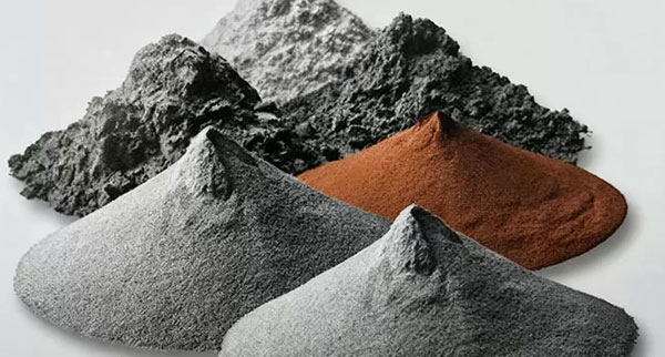
Conventional powder metallurgy parts are produced by blending metal powder, compacting it in a die, sintering the green compact, and applying only the secondary operations required by the drawing.
The press-and-sinter route is highly efficient for components that can be formed with top and bottom punches. Powder is metered into a die cavity, compacted under high pressure, ejected as a green part, and conveyed through a controlled-atmosphere sintering furnace. The Metal Powder Industries Federation notes that compaction pressure can reach approximately 50 tons per square inch for some press-and-sinter operations.
One of the process's strongest advantages is material utilization. MPIF states that more than 97% of the starting raw material can be incorporated into the finished PM component. This contrasts with subtractive machining, where chips may represent a meaningful portion of the purchased billet or bar. The process also supports multi-level features, splines, hubs, bosses, keyways, and gear teeth when the geometry remains compatible with tool movement and ejection.
Porosity is not always a defect. In self-lubricating bearings, interconnected pores store oil and release lubricant during operation. In structural components, density can be increased by material selection, pressing strategy, sintering conditions, sizing, repressing, infiltration, or other densification methods. The target should therefore be the density needed for the actual load case, not the highest possible density by default.
Hengji supplies engineered powder metallurgy parts for automotive and industrial mechanisms. Early design collaboration is especially valuable because a small change in wall direction, flange shape, chamfer, groove, or hole position can convert a costly secondary operation into a feature formed directly in the tool.
Geometry complexity is usually the first screening factor because MIM supports three-dimensional molded features, while conventional PM is limited by powder filling, axial compaction, and die ejection.
Conventional PM performs best when the part has a clear pressing axis. Features that are parallel to punch travel are easier to form. Radial holes, reverse tapers, deep undercuts, enclosed channels, severe wall changes, and threads perpendicular to the pressing direction may require machining or a redesigned geometry. Complex tooling can add levels and shaped punches, but each element increases tool cost, alignment requirements, and maintenance risk.
MIM can accommodate many features familiar to plastic injection molding, including ribs, cross holes made with cores, recesses, lettering, knurls, textured surfaces, and internal details. It is particularly effective when several tiny machined parts can be consolidated into one molded component. This part consolidation can reduce assembly labor, joint failure risk, inventory, inspection points, and dimensional stack-up.
Nevertheless, MIM geometry is not unrestricted. Very thick sections can prolong debinding and create differential shrinkage. Abrupt wall changes can distort. Long, unsupported features may sag in the furnace. Gate location can influence filling, weld lines, powder-binder separation, and cosmetic appearance. A MIM design should therefore use reasonably consistent wall thickness, smooth transitions, adequate draft, controlled aspect ratios, and sintering support where necessary.
Density and mechanical performance depend on material, porosity, heat treatment, geometry, and process control rather than on the process name alone.
MIM often reaches a high percentage of theoretical density because fine powder and high-temperature sintering promote pore closure. This makes it attractive for small structural components that need high strength, corrosion resistance, fatigue performance, or a polished surface. It also allows stainless steel and alloy systems that are widely used in medical, consumer, electronic, locking, and automotive applications.
Conventional PM generally retains more designed porosity unless a densification route is selected. For many gears, cams, pulleys, brackets, rotors, and structural components, the resulting properties are sufficient and economically attractive. The process can also create density gradients when geometry and tooling are not optimized, so the supplier must control powder filling, compaction ratio, part aspect ratio, and press motion.
Engineers should compare properties at the part level. Tensile bars provide useful material data, but a thin web, tooth root, sharp notch, cross hole, or unsupported boss can control real performance. Ask the supplier for the relevant material standard, target density, hardness range, heat-treatment condition, dimensional capability, and any test data connected to the actual application.
When fatigue, impact, pressure tightness, corrosion, magnetic response, or wear is critical, define the acceptance method in the RFQ. Examples include density measurement, metallographic porosity evaluation, hardness mapping, tensile testing, torque testing, salt-spray testing, magnetic testing, leak testing, or application-specific endurance testing.
Material selection must balance achievable properties, powder availability, sintering behavior, corrosion resistance, magnetic requirements, heat treatment, and total part cost.
Conventional PM is strongly established in iron and steel components, copper-based bearings, stainless components, and soft-magnetic parts. Material systems can be engineered through pre-alloyed powder, admixed alloying elements, diffusion-alloyed powder, carbon additions, lubricants, and sintering atmosphere. The final specification may include density, carbon content, hardness, strength, dimensional change, and microstructure.
MIM frequently uses stainless steels such as 17-4PH and 316L, low-alloy steels, tool steels, and selected nickel-based or specialty alloys. The exact grades available depend on the supplier's feedstock and furnace systems. Cross-contamination, carbon control, oxygen control, debinding chemistry, and sintering atmosphere are particularly important when corrosion or magnetic performance matters.
Do not select a material solely because it appears on a drawing inherited from a machined prototype. The original grade may have been chosen because it was readily available as bar stock rather than because its exact composition is necessary. A qualified PM or MIM supplier can propose a powder-based equivalent that meets the functional requirement more economically. Any substitution should be validated through engineering review and testing.
The lowest unit price is achieved when tooling investment, cycle economics, secondary operations, quality risk, and annual demand are evaluated together.
Both processes require dedicated tooling, so neither is usually the best choice for a handful of prototype parts unless a bridge-tooling strategy is available. Conventional PM tooling can include a die, core rods, upper and lower punches, and multiple levels. MIM tooling resembles a precision injection mold and may include runners, gates, slides, lifters, and interchangeable inserts.
Conventional PM can offer exceptionally high productivity when the part is pressable and annual demand is substantial. MIM cycle time at the molding machine can also be fast, but the full route includes debinding and sintering, and feedstock is generally more expensive than conventional press powder. MIM becomes compelling when its geometric freedom removes enough machining or assembly to offset those costs.
| Cost Driver | Favors Conventional PM When... | Favors MIM When... |
|---|---|---|
| Geometry | The part can be ejected axially with limited side features | The part has cross holes, undercuts, thin walls, or many integrated details |
| Material mass | The part is relatively heavy and geometry remains compactable | The part is small enough that complex value outweighs feedstock cost |
| Secondary machining | Little or no machining is required | MIM eliminates several machining operations or multiple assembled pieces |
| Annual volume | Demand supports high-speed compaction and dedicated tooling | Demand supports an injection mold and recurring debind/sinter batches |
| Surface and detail | Pressed surfaces and normal finishing meet requirements | Fine texture, small lettering, or molded detail reduces finishing work |
| Quality risk | Dimensional change is predictable along a pressable geometry | Complexity can be stabilized through mold-flow, shrinkage, and furnace control |
A proper commercial comparison should separate one-time and recurring cost. One-time cost includes tool design, mold construction, fixtures, gauges, samples, process validation, and potential tool changes. Recurring cost includes material, molding or pressing, debinding, sintering, heat treatment, machining, finishing, inspection, packaging, scrap, and freight. Compare the total annual cost at realistic production volumes rather than comparing only a quoted piece price.
Dimensional capability is the repeatable range a process can hold after all predictable changes from compaction, debinding, sintering, heat treatment, and finishing are included.
Conventional PM dimensions are influenced by powder apparent density, fill consistency, compaction pressure, elastic springback, tool wear, sintering shrinkage or growth, density distribution, and furnace conditions. Sizing can improve selected diameters, concentricity, or profile features after sintering. Machining remains appropriate for critical bores, threads, sealing surfaces, or geometric relationships that exceed net-shape capability.
MIM dimensions are influenced by mold filling, gate design, packing, cooling, binder removal, gravity during sintering, support fixtures, furnace uniformity, and material shrinkage. Because shrinkage is substantial, stable feedstock and precise process control are essential. Well-designed fixtures can support slender or asymmetric parts during sintering, but fixtures add cost and must themselves remain stable.
A drawing should distinguish functional dimensions from noncritical dimensions. Applying the tightest tolerance to every feature increases tool complexity, inspection effort, corrective machining, and rejection risk. Use geometric dimensioning and tolerancing to communicate datums and functional relationships. Ask the supplier to mark dimensions that are formed as-molded or as-sintered, those improved by sizing, and those requiring machining.
Production readiness means the selected process, tooling, control plan, measurement system, and supply chain can repeatedly meet the drawing at the required volume.
Prototype success does not automatically guarantee stable mass production. A robust launch should include drawing review, material confirmation, design-for-manufacturing feedback, tool design review, sample submission, dimensional report, material certification, capability studies for critical characteristics, control plan, packaging validation, and change-management rules.
For automotive programs, the required documentation may include PPAP elements such as process flow, PFMEA, control plan, measurement-system analysis, capability results, material and performance tests, appearance approval where relevant, and part submission warrant. The exact level should be agreed before quotation because the documentation burden affects lead time and cost.
Hengji reports that its first-process qualification rate improved from 98.45% to 99.31% after implementing an integrated quality-management approach. This is company-reported performance and should be evaluated together with project-specific evidence such as sample results, inspection records, traceability, process capability, and corrective-action response.
For buyers evaluating mim manufacturing for automotive components, the supplier audit should cover feedstock traceability, mold maintenance, debinding control, furnace calibration, sintering fixtures, dimensional inspection, material testing, lot segregation, and contingency capacity.
Application fit is determined by the combination of geometry, load, material, volume, and eliminated operations rather than by industry label alone.
The part includes two cross holes, a curved hook, a thin rib, identification marks, and a corrosion-resistant surface. Machining it from bar stock would require multiple setups, and conventional PM would need side machining. MIM is likely the stronger candidate because it can integrate most features into the mold and achieve high density in a stainless grade.
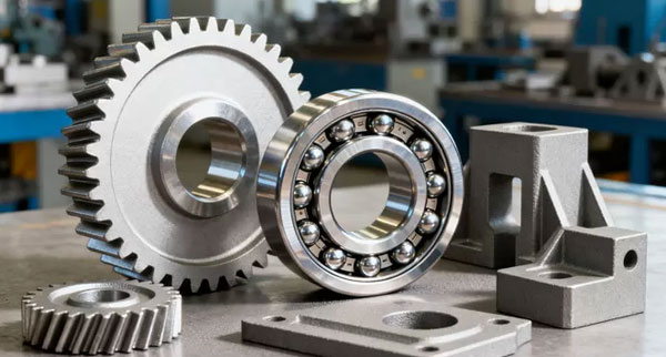
The gear has a central bore, hub, sector teeth, and a geometry aligned with the pressing direction. The application requires repeatable torque transfer but does not require full wrought density. Conventional PM is likely to provide lower total cost, high material utilization, and direct tooth formation, possibly followed by sizing or heat treatment.
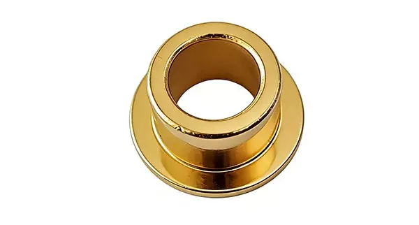
The component must store lubricant within interconnected pores and deliver it to the bearing surface during operation. Conventional PM is the natural choice because controlled porosity is a functional requirement. MIM's higher-density objective would not create the same oil-storage structure.
The part has multiple poles, thin bridges, and a three-dimensional magnetic circuit. Either route may be feasible. Conventional PM can be excellent for axial features and high volume, while MIM may be justified if the geometry cannot be compacted without extensive machining. The selection should include magnetic property targets, density distribution, eddy-current considerations, and dimensional validation.
The existing design may not be optimized for either powder route. The supplier should first perform a redesign study. MIM may consolidate several milled features, while conventional PM may reduce cost if side details can be moved, simplified, or formed in the pressing direction. A small design change can have more impact than a long negotiation over unit price.
A process selection framework converts drawing requirements into objective manufacturing decisions before tooling is committed.
Can the part be ejected along one main axis? If yes, conventional PM remains a strong candidate. If cross features and undercuts dominate, investigate MIM.
How complex is the component relative to its mass? Small, feature-dense parts usually create more value for MIM than large, simple parts.
Is porosity acceptable, beneficial, or prohibited? Controlled porosity may benefit bearings; pressure-tight or high-fatigue applications may require higher density or secondary densification.
Which material properties are mandatory? Define strength, hardness, corrosion resistance, magnetic behavior, wear, impact, and heat-treatment condition.
What annual volume and program life are realistic? Tool amortization changes dramatically between 20,000 parts and two million parts.
Which operations can the selected route eliminate? Count machining setups, assembly steps, welds, inserts, finishing, inspection, and handling.
How will critical characteristics be validated? Confirm measurement methods, sample size, capability expectations, and performance tests before quotation.
If the answers are mixed, ask the supplier to quote two concept routes with transparent assumptions. One option may minimize tooling while the other minimizes piece cost. A break-even calculation can then show which route is better at each volume level.
A complete RFQ gives the supplier enough technical and commercial information to propose a process, material, tooling concept, validation plan, and realistic price.
Provide a controlled 2D drawing and a clean 3D model with revision status.
State annual demand, order frequency, peak monthly demand, program life, and expected ramp-up.
Identify current manufacturing method and the operations you want to eliminate.
Separate critical-to-function dimensions from reference or noncritical dimensions.
Define material properties rather than only a legacy material name where substitution is possible.
List heat treatment, coating, plating, passivation, polishing, or appearance requirements.
State required standards, PPAP level, certificates, traceability, and change-notification rules.
Describe the operating load, temperature, lubrication, corrosion exposure, duty cycle, and failure mode.
Include packaging, cleanliness, burr, particle, rust prevention, and delivery requirements.
Request separate prices for tooling, samples, gauges, fixtures, recurring parts, and optional secondary operations.
Do not hide the application from the manufacturer. A supplier that understands the mating components and failure consequences can recommend better datums, radii, density targets, tolerances, and inspection methods. Confidential information can be protected through an appropriate agreement while still sharing the functional context needed for engineering.
A hybrid strategy combines near-net-shape forming with targeted secondary operations to meet only the characteristics that cannot be achieved economically in the base process.
Process selection does not need to be all or nothing. A conventional PM component may be compacted and sintered near net shape, then sized, heat treated, ground, honed, or machined only at a sealing face or precision bore. A MIM component may be molded with all major geometry and then undergo coining, grinding, laser marking, passivation, heat treatment, or limited machining.
The best hybrid route is usually the one that confines expensive operations to a small number of functional features. For example, it may be economical to mold a complex body and machine one threaded hole rather than machine the entire body. Likewise, a PM gear may be pressed with finished teeth and then ground only on a critical journal.
Hybrid routes require clear process sequencing. Heat treatment can change dimensions. Plating can build thickness. Machining can expose pores. Impregnation can affect cleanliness. Every downstream process should therefore be included in the dimensional and risk analysis from the beginning.
These frequently asked questions address the practical issues buyers most often raise when comparing MIM with conventional powder metallurgy.
MIM often achieves higher density than standard press-and-sinter PM, which can support higher strength for some alloys and geometries. However, strength depends on material, heat treatment, residual porosity, section design, and test direction. A densified PM part may outperform a poorly designed MIM part, so compare validated part-level properties rather than process labels.
MIM feedstock and processing can be more expensive, but the total part may cost less when MIM eliminates machining, assembly, or multiple purchased components. Conventional PM is often more economical for simple, pressable, high-volume shapes. A total-cost comparison should include tooling, secondary operations, scrap, inspection, and annual volume.
MIM is generally most attractive for small to medium components with high geometric complexity relative to their mass. There is no universal maximum because material, wall thickness, debinding route, furnace capacity, and economics vary. As part mass increases, feedstock and cycle costs become more influential.
Yes. Conventional PM can form spur gears, sector gears, internal gears, splines, hubs, and multi-level features when they are compatible with axial compaction and ejection. Cross holes, undercuts, and reverse tapers may require redesign or secondary operations. Tooling review should occur before the drawing is frozen.
Both processes can produce precise components within an appropriate capability window. Conventional PM may use sizing to improve selected dimensions; MIM depends on stable shrinkage and sintering support. The correct question is whether the supplier can demonstrate capability on the critical dimensions after all downstream operations.
Hengji needs the 2D drawing, 3D model, material and property requirements, annual volume, program life, critical dimensions, application loads, finishing requirements, validation level, and target schedule. Sharing the current production route and cost drivers also helps the engineering team identify opportunities for feature consolidation or redesign.
The best manufacturing process is the one that repeatedly delivers the required function, quality, capacity, and total cost over the full program life.
Conventional powder metallurgy is usually the stronger choice for high-volume components with a clear pressing direction, efficient material use, and limited side features. Metal injection molding is usually stronger for small, intricate parts that can consolidate machining and assembly. Neither conclusion should be made from a keyword, a material name, or a preliminary unit price alone.
Begin with geometry, density, material properties, tolerance, annual volume, and eliminated operations. Then evaluate tooling, process capability, validation, and supply risk. Hengji can review both process routes and provide design-for-manufacturing feedback before tooling is released, helping buyers avoid a costly process change after the product enters validation.
The following sources provide additional technical context for powder metallurgy and metal injection molding.